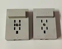
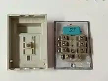
WT-4 (adopted under the name РТШ-IV in the USSR) is a Polish telephone plug used to connect telephone sets to the network. Introduced in the second half of the 20th century and adopted in several Eastern Bloc countries as a standard. It has since been replaced by the RJ-11 standard. Sockets are labelled with the text GTN-4.
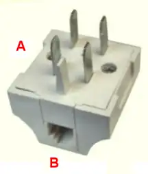
WT-4 plugs consist of 4 metal pins with an additional plastic pin at the bottom to prevent inserting the plug the wrong way round. When the plug is inserted into a socket, the plastic pin also disconnects a 1μF capacitor built into the socket. When connected, the capacitor simulates a telephone set with the handset hung up. This allows for the testing of the line even when the subscriber doesn't have a telephone connected to the network. In the mid-1990s, installations of WT-4 plugs began to be phased out, and the standardised shape of the socket was used to install RJ-11 connectors instead.
| Pin number | Function | Notes |
|---|---|---|
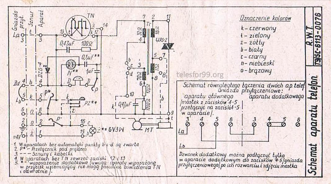
| 3 | Telephone line A | |
| 4 | Bridged with pin 5 in the socket | Used to connect an additional bell after removing a jumper wire in the socket |
| 5 | Telephone line B | |
| 6 | Ground | Used in sets with grounding buttons when working with internal telephone exchanges |
A rare 6-pin version also existed, called WT-6. Extra pins (numbered with the missing 1 and 2) were located between the existing pins 3 and 5, and 4 and 6, respectively. These extra pins were used for powering telephone sets with illuminated rotary dials, as well as some more advanced telephone installations.
See also
References
- Biuletyn Informacyjny Teleelektroniki, nr 2 / 1974
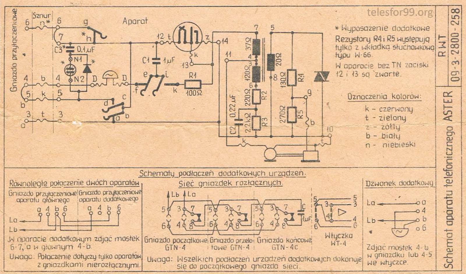
- Schemat telefonu Aster (prod. Radomska Wytwórnia Telefoniczna)
- Schemat telefonu CB-662 z podświetlaną tarczą